SECTION D38 - TASK 38
3D Cad modelling methods for cylinders. UCS's, Chprop, & Thickness.


Task Thirty Eight
An alternative method for doing cylindrical items
For future reference, there is a second way of producing cylinders like the hole in
task 37. It is sometimes useful, but has disadvantages. Here's how it's done:-
Make layer 01 (red) the current layer. Re-instate the default Wcs by using
the UCS command and accepting the W default. Position a circle (radius 10mm / 0.4 ins)
on the box face that had the cross on it, 25mm / 1 inch from the edges of the face with
the circle and the face with the oblong. (Draw the circle on an end, and
then move it using the @X,Y,Z method) See fig TSK 38.
Give it a Chprop - thickness of 15mm / 0.6 ins. Having added
this cylinder to the assembly, the modelling is now complete.
The disadvantages of this cylinder lie in the number of vertical entities that appear on it. Too many cylinders like this can quickly make a model over complicated and difficult to read - even after a hide. There is a setvar variable to minimise these entities on screen. Some versions also have disadvantages when plotting by filling in these cylinders when they ought to be in outline only.
Both methods of creating cylinders have drawbacks relating to unwanted entities. This cylinder shows the worst case for unwanted entities. The preferred method for cylinders was shown with the green component's drilling and the yellow component's shaft, but these also suffer from unwanted entities. With the preferred method for cylinders, the disadvantages won't become apparent until task 41, where they will be discussed in context. Work around solutions for cylinders are described in Appendix I.
Save your work and move to the next tutorial.
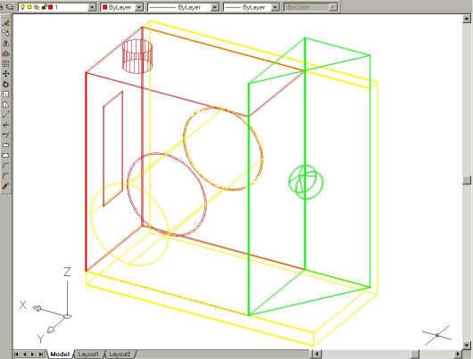
Fig Tsk 38. An alternative method for a cylinder as shown on top of the box.
Tutorial 3
Task 39 on the next page is the start of Tutorial 3.
Tutorial 3 is the key to understanding professional 3D design, because it shows the foundations
for the 3D design process that is referred to on the home page. For a 3D design to follow the
3D design process effectively - and thus retain high integrity - it MUST be worked on
and manipulated in its "assembly" condition and NOT as a bunch of individual components.
Despite remaining in an assembly condition it is very easy to show and dimension individual items.
Tutorial three shows exactly how it's done. It begins by demonstrating how to manipulate projection
views more thoroughly than was shown in task 12 and 14. Competent view manipulation is important for
two reasons.
1./
Re-configuring views in case of any "human mistake" projection errors that need rectifying.
2./
To create formal drawing projections of individual components while still part of
the "High Integrity" assembly.
Layering methods are shown in detail, and an auxiliary view is also created.
Now move to the next page by using the circular arrow icons below and continue with Task 39.
Please feel welcome to make use of the free resources at the side and bottom of these webpages. Many of them contain very useful 3D CAD material.


For a negligible fee (about the cost of a large cola drink) the full course AND CERTIFICATE can be printed in one go. The small sums it raises cover our costs for running the site. Click here for details.