SECTION D46 - TASK 46
Detail drawings with 3d Autocad. Component layers and Xref.


Task Fourty Six.
3D Methods and detailing.
Ideally, detail drawing creation should happen after a model has been finalised because premature creation of projection drawings will reduces software speed - particularly if a design is still evolving. Although preferable, it's not always practical to complete the CAD models prior to detail drawing because large models also reduce the software speed. However, large models can be split into sub-models in accordance with the ASSY layer and ASSY block conventions described in "Layer Management For Complex Designs" between tasks 41 and 42. When a design starts to become firm, make each major assembly a separate model. i.e. Wblock each assembly to exist as independent sub-models. (The blocks can then be inserted in to other models, or the "Xref" command can be used to reference these main assemblies back together when needed. If Xref is an unfamiliar command, read about it in the AutoCAD documentation, or the on-line help, and experiment with using it.) Each major assembly would then become the responsibility of a Section Leader on the project. This method of splitting models is discussed further in Section G of this website.
When a model is ready for detailing, dimensioning is generally going to take place in the drawing environment. Some situations need to be highlighted.
1.
When working in the drawing environment, dimensions and other drawn
entities will not appear in Modelspace, unless entered within an active Mview
window. Once an Mview is active, any entities added in it, including dimensions,
will become model entities.
As with other entities, dimensions can only be edited in the environment where they are created. Dimension entities in the drawing environment don't show up in the modelling space and modelled dimensions only show up in the drawing environment when viewed through Mview Viewports, because they would be part of the model.
2.
Since Mview Viewports are scaled, dimension entities need to
accommodate this. Newer software does it automatically, but older software
uses a specific AutoCAD variable - its easy. The issues for older and
newer software are covered in a moment.
3.
For older releases of Autocad, dimensions lose their associativity
in the drawing environment when attached to model space entities - this is a
nuisance.
A balance needs to be struck between dimensioning in Modelspace and dimensioning in Paperspace. Dimensioning exclusively in Paperspace is the most preferable but only when the design is finalised. If detail drawing is started while design modelling is still happening, the computer slows down. To compound the situation, further man hours are lost by continually up-dating drawings while the design evolves.
Hidden detail lines will not be covered in this section. Since a 3D object can be viewed from any position, and views easily defined, hidden detail lines become redundant. Define as many views, and choose them carefully, so that the component can be detailed without the need for hidden detail. In the event a situation occurs that necessitates hidden lines, using them is discussed in appendix 1. Remember to plot with the "Hidden line removal" option invoked as follows:-
Some releases of Autocad allow hidden line removal in the plot
window. However, it can cause text fill and arrow head fills to be
removed. Other releases need to have it set in the drawing environment
by using mview > h > on > select objects.
(Mview borders will need to be visible to select them.)
It is wise to perform a screen Hide before plotting to check out what will plot.
A screen hide doesn't ensure a hidden plot. It is just a visual check. If 3D methods are to be used regularly, it is wise to make hidden plots a default setting. This would be done by changing the AutoCAD reference drawing template - usually called ACAD.DWG. One of the "config" menus will display the name of the template drawing.
Task 46.
Remain in the drawing environment and ensure none of the Mview windows are active. The Mview borders need to be visible so turn on layer VPL. Set the current layer to 08. Layer 08 should be a grey shade and the colour defined on the plotter menu as medium thickness. It is often desirable to have dimension text heavier than the dimension lines. Dimension text can be set to a heavier thickness by changing the text colour using the "Dimclrt" Setvariable. Set the value to 7 (white), starting NOT from the "Dim:" prompt - but from the "Command:" prompt - as follows:-
| Autocad Command Sequence | Note |
| Command: dimclrt > | |
| Enter new value for DIMCLRT: 7 > | |
| Command: save > | |
|
|
|
Zoom to the layer 1 red component. Its base was 125 x 75 (5 ins x 3 ins.) Ignoring the fact that the Mview border is still visible, dimension the overall size of the box in the plan view and read to the end of the paragraph. The scale of dimensions is controlled by a setvar variable called dimlfac and it varies for different releases - older versions need dimlfac to be set by the user to match the zoom scale of the viewport being dimensioned. Newer releases handle dimlfac scales automatically. If the dimensions show 125 (5 ins) and 75 (3 ins) then the dimlfac scaling was automatic and it is possible to skip to the bottom paragraph. However, it is wise to read the interim steps below to understand the issues.
If the dimensions are something other than 125 and 75 (5 x 3 ins) - probably half values instead - dimlfac needs to be set. (Remember the Zoom scale of these views should still be set to 0.5XP and the impact of the XP value on dimensioning will become clear by example.)
Dimlfac can be set from the "Command:" prompt or the "Dim:" prompt. Starting from "dim" offers an advantage discussed in a/ below. Proceed as follows:-
| Autocad Command Sequence | Note |
| Command: dim > | |
| Dim: dimlfac > | |
| Enter new value for dimension variable, or Viewport <1.000>: v > | a./See a./ |
| Select viewport to set scale: (Pick the border of the plan viewport.) |
|
| DIMLFAC set to -2 | |
| Dim: | |
| Type EXIT to return to COMMAND prompt. | |
| a./ When dimlfac is set from the "Command:" prompt it is not possible to pick the viewport, only to enter a value manually. Using the "Dim:"prompt and picking the viewport ensures that the dimlfac value will always match the viewport - particularly if there was a mistake when setting the Zoom scale. |
|
Dimensioning the base again will give the appropriate values of 125 and 75 (5 x 3 ins.) Every Viewport that is at half scale could now be dimensioned.
The Dimlfac variable is related to the XP Zoom scale of the Viewports. The example above using the base of the box, dimensioned a Viewport with an XP Zoom scale of 0.5 (0.5XP.)
To learn more about what to expect from your software version, and deduce how it behaves with the XP and Dimlfac relationship, zoom to some empty space on the screen to do the following short exercise.
Define four more Mviews using the command Mview > 4 >. Activate each in turn to restore view 1 (Task 5 for restoring views) and set some strange XP values. (Values can be set two ways; by typing odd values like 0.384XP or by zooming in an active Viewport.) Once all four Viewports have different zoom scales, de-activate them and then dimension the red box in each viewport. With newer software, the dimensions should be correct for every viewport, but older software gives strange values. If your dimension values are correct, skip to the paragraph after the note below. If they were not correct, then continue.
Initiate the Dimlfac > v command once more on ONE of the viewports and notice the Dimlfac value that AutoCAD returns. Note it down and dimension the viewport. It should now return the correct dimensions. Do this for the other 3 viewports and deduce the relationship between the Dimlfac value and the Zoom XP value. Understanding this relationship will help when controlling the scale of views. (For Viewports with an arbitrary zoom, use "List" to obtain the XP value before making the comparison. There is a strong chance your software has the relationship that dimlfac = 1 / xp.) Ensure no Mviews are active.
NOTE.
When using Viewports on older software, remember TO SET THE DIMLFAC VARIABLE.
If enlarged views such as 2 x full size reside with reduced views like 0.5 x
full size, the Dimlfac variable will need re-setting every time a Viewport of
different scale is detailed.
For the purposes of the next task, zoom to the triangular component on layer 3 and dimension the position of the hole. State the size and depth of the hole using a leader arrow as shown in fig Tsk 46. (Hole details were diameter 20 x 10 deep - 0.8 x 0.4 ins - Task 37) Save your work. Apart from Dimlfac and lost associativity on older software, the dimensioning is generally the same as traditional 2D methods. There might be other minor problems on older software, but they will not be a major hindrance, just a minor nuisance.
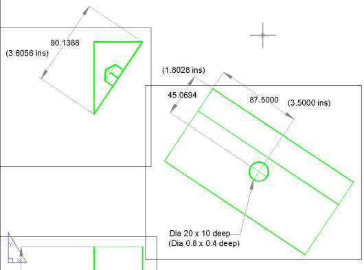
Fig Tsk 46.Dimensioning the hole on the auxiliary view
Please feel welcome to make use of the free resources at the side and bottom of these webpages. Many of them contain very useful 3D CAD material.


