SECTION D47 - TASK 47
Up issuing Autocad models and drawings. Layers and Pspace.


Task Fourty Seven.
Managing issue levels.
As a design progresses, modification and up-issues are bound to occur and the model must always reflect the latest issue. When an up-issue happens, the outdated parts of the design, both model and Pspace entities, have to be assigned to an "ISS ## " layer. The following section shows how components can be modified and up-issued after using the "CMPT" and "ASSY" block procedures in tasks 43.
In a hypothetical situation, assume that a design contains 58 components. This can be deduced because the last CMPT layer is 58. They are arranged to give three assemblies, since the last ASSY layer is ASSY03. The entire design exists as "ASSY" blocks and "CMPT" blocks.
Starting from a complete model fully displayed, the goal is to identify the assembly that contains the component for modification. This can be done by using the "list" command. Having used the List command on the desired assembly, assume that the layer name returned was layer ASSY01. At this point the user would freeze the unwanted ASSY02 and ASSY03 assembly layers so the model is de-congested with only the ASSY01 assembly displayed.
Imagine, by pure coincidence, that the left over assembly being displayed on layer ASSY01 is a three component affair with a red box, a green wedge, and a yellow angle - just like the one modelled so far.
Now that the two hypothetical assemblies are out the way the up-issuing work can begin. The green wedge component needs to have its hole made smaller in diameter but deeper. Proceed as follows:-
Zoom a window that contains the assembly and activate the
pictorial view.
Explode the assembly block. Use "List" to identify the layer name
of the green component, in this case its layer CMPT03.
Enter the full modelling environment by picking the model tab at the lower left of the screen, or by typing tilemode - 1. For reasons described in the section between task 41 and 42 headed "Layer management for complex designs," green components reside on layer 03, SO MAKE LAYER 03 THE CURRENT LAYER. Freeze all the CMPT layers except CMPT03, and leave all the entity and ISS# layers on. The component is now the only image on the screen. Explode the CMPT03 block. Change the layer of the two circles and all the other entities that represent the drilled hole, to layer "ISS01"
Work in the pictorial view but refer to fig TSK-47 as a guide to carry
out the following steps:-
Step 1.
Restore UCS 7 with ucs >r > 7 and construct a new hole on
the face at the center of the existing one. (The original drilling was
constructed in task 37.) Use a radius of 5 (0.2 ins) for the new hole.
Step 2.
Copy the new circle to a depth of -15 (-0.6 ins) in the
"Z" direction.
Step 3.
Insert a line from one of the horizontal quadrants of the
new circle at the surface, to the corresponding quadrant of the new buried
circle. Set the Ucs to its World position using ucs > w
Step 4.
Restore view 1, (plan view), and zoom as needed. Draw a line from
the existing "point" (labelled "Point A" in fig TSK 47), to where the new
quadrant line intersects the existing 30 degree line, (labelled "Intersect B").
Step 5.
Restore the pictorial view 71 and freeze layer ISS01. Move the new
"point representation" entity (created in step 4) to the buried end of the
quadrant line shown at step 5 in fig TSK 47. Restore Ucs 7 and generate an array
of 4 for the quadrant and point representation entities about the circles' axis.
Switch back to the drawing environment and ensure no Mviews are active
(Don't re-create the CMPT03 block just yet.)
Zoom out and then zoom a window around the lower right A3 sheet that contained the original detail views of the green component. (Don't confuse other views showing the green component with the original detail view.)
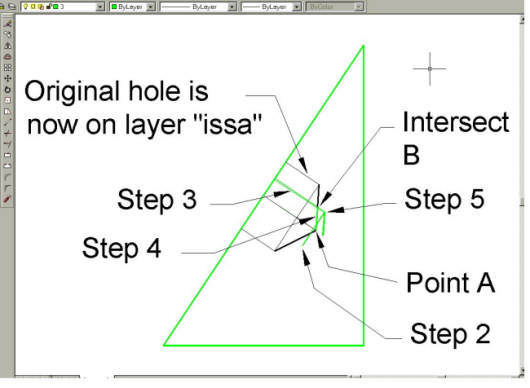
Fig Tsk 47.
Modifying the hole for up-issuing.
Note.
All the views will show the green component at this stage. It is displayed
at the moment because it is currently a layer 03 part. The visibility of
the part is controlled by the visibility of the layer on which the block
CMPT03 resides. The visibility of the part will rectify itself when the block
is re-defined on layer CMPT03.
Use the "Chprop" command and pick the leader arrow and text that has the original hole data and assign them to layer ISS01. It will disappear because layer ISSA is frozen. Define a new leader arrow with the correct hole data on layer 08 - diameter 10 x 15 deep (0.4 x 0.6 ins.)
The CMPT and ASSY blocks can now be re-established. Do the following steps paying particular attention to current layer and block names:-
1.
Activate an Mview and reset to the Wcs if it isn't already set to Wcs. Make the
CMPT03 layer current. Re-invoke the block command and re-define block CMPT03
ON LAYER CMPT03 at 0,0. (Answer Y to the "Redefine it?"prompt.)
Take care to pick only wedge related entities. If other entities or blocks are selected accidentally they will inadvertently become part of the CMPT03 block and result in disappearing from Mviews that should show them. It is IMPERATIVE that a block resides only on its relevant layer of the same name.
2.
Deactivate the Mview and thaw all the CMPT layers. Zoom out so all the
Mviews can be seen.
If some Mview displays become blank unexpectedly, or unwanted components appear in the wrong viewports, the first check should be that the block-name / layer-name relationship has not been violated. Use the Undo command and re-trace the tutorial instructions carefully.
Zoom into the four assembly Mviews and re-activate a view.
3.
Make the ASSY01 layer current and re-block the assembly group of
components - CMPT01, CMPT02 and CMPT03 - including the modified
component. (Answer Y to the "Redefine it?" prompt.)
To see the original issue A design, simply unfreeze the ISS01 layer. Since the ISS01 layer is the latest layer entry, it follows that the current component must be at ISS02. Carry out all plotting with the "hidden line" option invoked and all ISS# layers frozen.
Now that the need to activate and deactivate mviews has subsided, the Mview borders can be removed from the display by freezing layer VPL. Save your work to complete the tutorial. We strongly advise doing the training a second time. You will be able to do it much quicker, and far more is absorbed when done a second time.
Using 3D for 'Real.'
The starting point for a real 3D design is to create assembly models. Start the models on entity layers, and when a part or assembly becomes firm create a block and layer with the name the same as the part number. In the absence of real part numbers, use cmpt and assy descriptions as per this training. When the 3D assembly models are at a suitable stage - as finished as possible but only you can judge - then use them to create drawings and parts lists.
Having completed these tutorials, enough understanding should have been gained to tackle any 3D design that requires regular shaped objects. Irregular complex objects with curvature can be tackled but require much more thought about construction. If complex curved shapes occur regularly, upgrading to better software would be beneficial. Having gained an understanding of how 3D methods are applied, do not be afraid to experiment with other 3D commands; particularly commands to create solids as well as Polylines, Meshes, and the many commands ending in "Surf." Work with these commands to create elaborate part models. Once modelled, they can then be handled in the same way as was done with the simple models in this tutorial. Congratulations in achieving a higher standard of AutoCAD professionalism and good luck with your new abilities.
Note.
The layering methods shown in these tutorials allow components to be shown individually
while still part of an assembly. Other 3D software packages are able to show components
individually in the same way but do not rely so heavily on layering methods to achieve
it. The important point is that components need to be displayed while still part of an
assembly. Autocad achieves it using layers, other software often uses other methods.
Please feel welcome to make use of the free resources at the side and bottom of these webpages. Many of them contain very useful 3D CAD material.

