SECTION D12 - TASK 12
Learn 3D Cad FREE online. A 3D Cad online course modeling shapes on a 3D box


Task Twelve
The purpose of tasks 10 and 11 were to give an introductory overview of how projections are derived. As 3D methods become more natural, aligned scaled projections can be derived at any time.
Note
The way the Mviews display the model during task 12, such as all of the model, a
partly obscured model, or a fully obscured model, can be completely ignored at
the moment since the task is concerned with the size and position of the Mviews, and
the size of the drawing Environment - tilemode 0. This task is necessary for preparing
the drawing environment prior to setting up aligned, scaled projections.
Early on in the life of a design the limits command needs to be used and was done so in
task 1 for the modelling environment - tilemode 1. Exactly the same needs to happen in
the drawing environment, so that the Mviews and other detailing entities lie within the
limits. Entities existing beyond the boundary of the limits isn't unusual but isn't good
practice either. Setting the limits in the drawing environment is done exactly the same
way as for the modelling environment.
As the task unfolds, some users may find that their Limits are already set to the
appropriate values. This may depend on the release of AutoCAD being used. Even if
this is true for your version, continue the task through to its conclusion.
The views created in tasks 9, 10, and 11 will be within some arbitrary limits for
the drawing environment and these limits could currently be any value. Limits can
often be set independently in both environments and needn't be the same as each
other.
However, in this case it is convenient to make them the same, so the limits for the drawing environment will also be as an A3 sheet, (B size) approx 420 x 300. (17 ins x 11 ins) Ensure Pspace is active - by checking the Ucsicon is triangular, and that no views are active - and proceed with the limits command as follows:-
| Autocad Command Sequence | Note |
| Command: limits > | |
| Reset Paper space limits: Specify lower left corner or [ON/OFF] <0.0000,0.00000>: > |
|
| Specify upper right corner: <xxx,yyy > :17x11> (ISO = 420,300) > | a/ |
| Command: | |
| a. xx and yy represent your current values. Do not do any zooming until prompted to do so. |
|
Some users, (depending on the software release being used) may have found these limits values already set, and should continue with the task to gain an understanding of what is happening. Having set the limits, 3 outcomes may result. Establishing which result cannot be achieved until a "Zoom all" is performed in a moment. However, the outcomes will be ONE of the following:-
1.
The new limits are larger than before and the Mviews become smaller and locate themselves
toward the lower left hand corner. In extreme cases the Mviews can become very small and
seem to vanish. The smaller Mviews outcome is fairly probable.
2.
The new limits are smaller than before so the Mviews appear to be about the same size.
Soon, when the Grid is turned on, it may be too dense to display suggesting that the Mviews
are too large. This outcome is also fairly probable.
3.
The limits were already set to 17x11 (420,300) and the Mviews are well spaced approximately
in the middle of the limits. The screen seems unchanged. This outcome is also a possibility
for some users, depending on the software version.
Before doing the Zoom all, it is useful to see the area of the limits. This is done using the "Grid" command because the grid dots are displayed only within the confines of the "limits". Proceed as follows:-
| Autocad Command Sequence | |
| Command: grid > | |
| Specify grid spacing(X) or [ON/OFF/Snap/Aspect] <0.500 >: 0.2 > (IS0 = 5) | |
| Command: |
Note
Look closely for the grid dots. They may be very spread out. If the grid dots don't
appear, or are too dense to display, continue anyway because the situation will clarify
itself soon. Try and deduce the size of the MVIEWS relative to limits you are using.
Perform the Zoom all to see the results of the limits command.
The 4 Mviews will equate to one of the outcomes 1, 2, or 3 discussed above. It is easy
to deduce which outcome based on any AutoCAD massages and the following facts:-
* If the grid is too dense to display, the Mviews are far to large.
* If the Mviews reduce in size, (or seem to vanish), the Mviews are far too small.
They may be residing in the bottom left corner of the screen. Zoom in to see.
* If the display remains as before and the grid is also visible, the Mviews are a
suitable size.
Having deduced the outcome, the Mviews will need manipulating so they are spaced approximately in the middle of the limits grid. Read to the end of the task for guidance on manipulating Mviews, and then return again to this part of the text to manipulate the Mviews according to the instructions.
Note
If the display remained unchanged and the views are already in the middle,
THEY SHOULD STILL BE MANIPULATED for the sake of practice. Manipulation is used again
later, so scale them down slightly and move their position a little.
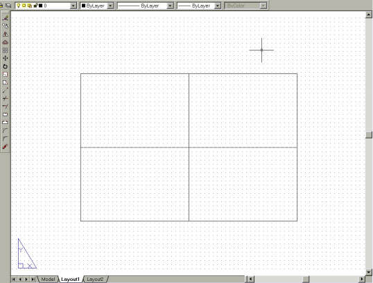
With your existing AutoCAD skills, use the Scale command and the Move command to re-size the Mviews neatly within the middle of the grid. Fig TSK 12 shows the approximate screen layout with regard to Mview proportions that should result.
You will find the image within each Mview gets disrupted or even vanishes - continue anyway.
Note
The Mviews' size relative to the grid is the important factor in this task, NOT what is
shown within the Mviews.
When using the Move / Scale commands and prompted to "Select objects," select the Mviews by picking the borders. When using Scale, don't worry about losing the box image from within the Mview windows as this will be dealt with in the next task. While using the Move and Scale commands, it is completely acceptable for Mviews to overlap, although this shouldn't be necessary. Now return to the paragraph above the note on the previous page and carry out the instructions. When the four Mview windows, empty or otherwise, are positioned within the A3 size limits, turn off the grid.
Note
A Grid may already exist in some of the Mviews that were defined in task 10. If the grid is
still switched on in the modelling environment it can be left on. If you wish to switch it
off, you need to activate the relevant Mview window and invoking the grid command with F7.
Once complete, switch back to drawing environment (using Pspace or double clicking) before
starting task 13.
Please feel welcome to make use of the free resources at the side and bottom of these webpages. Many of them contain very useful 3D CAD material.


