SECTION D9 - TASK 9
FREE 3D Autocad instructions. A 3D Autocad model and projection views. Learning 3D
Cad


Task Nine
At some point while learning 3D Cad, traditional orthographic projection views will be needed from the 3D Autocad model to create proper 3rd angle projection drawings. (Or 1st angle projection drawings.) This task deals with orthographic projection views so read and follow these 3D Autocad instructions VERY carefully.
Note
For those using older equipment, if the screen does not match the descriptions or
diagrams, complete the tutorials on a more powerful PC.
For newer versions of Autocad, some more settings need to be in place so the software responds in accordance with the tutorial instructions. Older Autocad software is already set to behave as required. If your Autocad software does not have a 'Tools' heading in the top menu bar (see Fig Tsk 9a) the next 2 paragraphs and 2 diagrams do not apply. However, read them anyway for reference and continue the tutorial from the paragraph that starts "The creation of projection views could..."
If there is a 'Tools' heading in the top menu bar the 'options'
need to be set the same as Fig Tsk 9b. Fig Tsk 9a shows what to pick to get to the
'options' window in Fig Tsk 9b.
Fig Tsk 9a.
Pick 'tools' and then 'options' to open the 'options' window.
Fig Tsk 9b.
On the top tabs, pick the second one along called 'Display.' Look at the checkboxes in the 'Layout Elements' part of the gray panel and set them to match with Fig Tsk 9b.
The creation of projection views could now begin. However, an explanation about AutoCAD's two environments is needed. Understanding them, (called Tilemode - 1 and Tilemode - 0 on older software and Model tab / Layout tab on newer software at the bottom left of the screen), is an important part of these tutorials. (The Layout tab(s) appear just to the right of the model tab, and might have a name other than layout because it can be edited.) The two environments allow designing and detailing to become two distinct activities.
The first is the default environment Tilemode - 1 / Model tab and is used to create a 3D CAD model to represent reality as shown in tasks 1-8. There should be no center lines or dimensions on the 3D model. Treat it as an electronic prototype. It is the usual environment for creating 2D designs. The second environment is the Tilemode - 0 / Layout tab - sometimes called paperspace - and is used to create traditional drawings from the 3D model. (Occasionally, users configure Layout / Tilemode 0 as the default environment, but to ensure smooth progress of these tutorials, the environments were set up in task 2.)
These environments can be accessed two ways, by clicking the lower left tabs
for newer software, or using the 'Tilemode' commands for older software.
The two environments can be deduced by the shape of the UCS icon. In the model /
Tilemode 1 environment the icon shows the X and Y directions. The Layout /
Tilemode - 0 environment shows a triangular UCS. A summary of how to enter the 2
environments for both older and newer software is as follows, so
note down the
one that applies to you for use later on:-
Older software:-
Enter the modeling environment by typing 'Tilemode >' followed by
'1 >'
Enter the drawing environment by typing 'Tilemode >' followed by '0
>'
Newer software:-
Enter the modeling environment by clicking the 'model' tab at the lower
left.
Enter the drawing environment by clicking the 'layout' tab.
(The method for older software also works with newer software.)
You will need to refer to your notes on the above when asked to enter the modeling or drawing environments throughout this training.
Now enter the drawing and modeling environments in turn, and do not
worry if the entities seem to vanish when entering the drawing environment. Enter
each environment a few times. Look for the triangular icon when in the lower left
corner. (You might have to activate it by typing 'ucsicon >' followed
by 'on >.' Only the icon should be visible in the drawing environment /
tilemode 0.
If other entities are visible in the drawing environment, it is due to the
configuration of your particular machine and they should be erased for this
tuition. Zoom out, make sure all layers are visible, and erase all entities using
the 'crossing' window to pick everything. After the drawing environment is
empty, ensure you finish up in the modeling environment.
The component up to now has been in its design phase in the modeling
environment. It can be equated to being in the designers mind while creating a
mental picture of the design. The only difference is the design is not just in the
mind, it's on the screen as well.
Enter the modeling environment by clicking the 'model' tab at the lower
left.
Enter the drawing environment by clicking the 'layout' tab.
(The method for older software also works with newer software.)
After the design has been created, projection views are needed to convey the
object information accurately as a traditional projection drawing. It happens in
the Layout / Tilemode 0 drawing environment allowing the 3D CAD model to be viewed
as several projections without having to copy groups of entities. The views can
include pictorial images as well as projection images.
The drawing environment can be equated to the designers paper because it is where
detail drawings will evolve. To put it briefly:-
modeling environment is Tilemode 1 = Model Space = Mspace = Designers
mind.
Drawing environment is Tilemode 0 = = Layout/Paper Space = Pspace = Designers
paper.
There are only 2 environments. One for creating models and one for creating
drawings. Many different names exist like Paperspace, Pspace, Mspace, Layout,
Drawmode, Modelmode... etc. The different names probably arise because there are
different ways of accessing each environment. Mspace and Modelmode are a prime
example. They are both the modeling environment but Mspace is like a temporary
version, so It has been given this different name. It all becomes clear as the
Tasks unfold.
Creating projection views is a 2 stage process. Here is how the first stage is
done.
Firstly, enter the drawing environment. When the drawing environment is
active use the command shown below.
| Autocad Command Sequence | |
| Command: mview > | |
Specify corner of viewport or [ON/OFF/Fit/Hideplot/..etc../2/3/4] <Fit>: 4 > |
|
Specify first corner or [Fit] <Fit>: Pick near the lower left of the screen |
|
| Specify opposite corner: Pick near the upper right of the screen | |
| Regenerating model. | |
| Command |
The outcome should correspond to Fig Tsk 9c; four identical images of the model created in tasks 1-8. If not, read on.
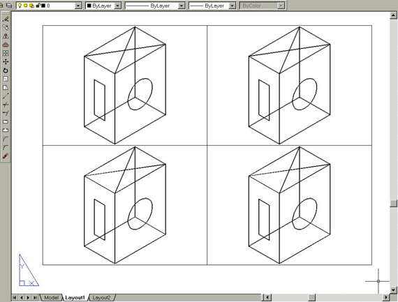
Fig Tsk 9c.
The 4 views are probably pictorial but not necessarily so. If each view displays something, all is well. Grid visibility at this stage is not important but blank views suggest the computer being used is not powerful enough. Try zooming.
Note If some of the four Mviews appear
empty, a system variable called Maxactvp governs the number of windows that can
display their entities at the same time. It was used in task 2 to set the number
to 8. It means 8 views are able to display images of the model.
If some of the
four views appear empty, ensure this value is still set to 8 by typing
"maxactvp".
AutoCAD will return the current value by showing it in
brackets. If the value is set to 8, and views still appear to be empty, the
indications are that a more powerful machine is needed.
Obtaining the four Mview windows completes the first stage of the orthographic process. many people know these Mviews as viewports. This training uses the name mview, but feel free to make a note that an Mview is the same as a viewport.
Please feel welcome to make use of the free resources at the side and bottom of these webpages. Many of them contain very useful 3D CAD material.


For a negligible fee (about the cost of a large cola drink) the full course AND CERTIFICATE can be printed in one go. The small sums it raises cover our costs for running the site. Click here for details.