SECTION D3 - TASK 3
FREE 3D Training in 3D Autocad. An Autocad course in 3D covering vpoint, ucs, wcs,
and polylines.


Task Three
Task 3 of our Autocad course in 3D is the start point for creating models in 3D
Autocad. Follow the free 3D training instructions carefully.
Without using
Polylines or Rectangle commands, draw a four sided regular shaped box size 5"
x 3" (ISO = 125 x 75 mm) in your usual way as if working in 2D, so that, when
completed, the box is approximately in the middle of the grid display.
Starting at the lower left corner of the box, a method of doing this is as
follows:-
| Autocad Command Sequence | Note |
| Command: LINE > | |
| Specify first point: (Pick somewhere to start the line) | |
| specify next point or [Undo]: @5,0 > (ISO = @125,0>) | |
| specify next point or [Undo]: @0,3 > (ISO = @0,75>) | |
| specify next point or [Close/Undo]: @-5,0 > (ISO = @-125,0>) | |
| specify next point or [Close/Undo]: C | a/ |
| Command: | |
| a. The 'c' stands for 'close.' Note the minus value in the line above it. | |
The Vpoint Command
The first command in 3D Autocad is "Vpoint" (short for 'view
point') and allows the user to see a model from a specific viewing position.
Understanding a viewing position is important when working in 3D Autocad and uses
the UCS (xy icon arrows) as a datum for deducing the viewing position. It will
become clear by example in the next few paragraphs. (The UCS is a picture
representation of the Cartesian Coordinate System. The Cartesian system is
explained in the next 'note' because understanding positions in 3D space
is linked with understanding Cartesian Coordinates.)
Vpoint is a very common 3D command that is fundamental for seeing the model
from different positions. It ALWAYS relates to the position of the viewer LOOKING
TOWARD THE DEFAULT UCS - THE WCS. (WCS is active at the moment and stands for
World Coordinate
System.)
Use the Vpoint command as follows:-
| Autocad Command Sequence | |
| Command: vpoint > |
|
| Current view direction: VIEWDIR = 0.00, 0.00, 1.00 | |
Specify a viewpoint or [Rotate] <display compass and tripod>: 1,1,1 > |
|
| Regenerating model. | |
| Command: |
The box is now shown from a diagonal position, almost filling the screen. Zoom out a little as follows:-
| Autocad Command Sequence | |
| Command: zoom > | |
Specify corner of window , enter a scale factor (nX or nXP), or |
|
| [All/center/Dynamic/Extents/Previous/Scale/Window] <real time>: 0.2x> | |
| Command: |
Now the display also shows the grid at a diagonal with the four sided box near the middle similar to Fig Tsk 3a.
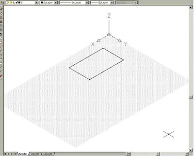
Fig Tsk 3a.
Fig TSK 3a shows how the screen display should appear AFTER the above steps but if it does not, the degree of Zoom in or Zoom out may vary depending on the level of CAD equipment being used. Zoom a little more if required.
A chosen viewpoint always sets itself to look toward the WCS,
so experiment with vpoint values and zoom out to see the full grid dots each time.
Try vpoint values of 1,2,3 and 3,2,1 and think about your position relative to
the UCS icon. Finish with vpoint 1,1,1.
Notice the view is looking toward the
Wcs origin from a position of 1X, 1Y, 1Z hence the 1,1,1 response to the Vpoint
command. The Wcs icon is still in its default position. The Wcs icon was at the
lower left of the screen before task 3 and all that has changed is the viewing
position not the Wcs position.
There can sometimes be confusion between Ucs and Wcs. The 0,0,0 location of the Wcs coincides with the limits position of 0,0. Since Wcs is the default plane, other planes are referred to as Ucs's. A Ucs is nothing more sinister than a localized Wcs, and seeing the X,Y,Z directions of a Ucs is very useful. If you understand the Cartesian Coordinate System move to task 4 of this free 3D training, or read on for more explanation because the UCSicon plays an important part of this Autocad course in 3D.
Note
The Ucsicon (User Co-ordinate System icon) in the lower left corner of the screen
is the start position of the Cartesian co-ordinate system for an AutoCAD. It is a
right angle shape with arrow heads showing X and Y (and Z on newer software)
directions. Fig TSK 3b below shows 2 icon styles and some numbers. Newer software
has the icon on the left, and older software has the wide arrow style. The numbers
on the right relate to "X" and "Y" distances discussed
below.
A position in space can be identified by its X, Y and Z distances relative to the
icon. (The Z axis points out of the screen toward the user when the icon is in the
position shown in Fig TSK 3b, so when an axis is difficult to display, it
isn't shown on the icon.) The three X, Y, Z axis' start at a point zero
along the X axis, zero along the Y axis and Zero along the Z axis. It is called
the origin and an origin is always at a position 0X,0Y,0Z. It means distance zero
in the X direction, distance zero in the Y direction, and distance zero in the Z
direction.
An single point might exist near the 0,0,0 origin at a distance of 5mm in the
horizontal 'X' direction, 3mm in the 'Y' direction and 2mm in the
'Z' direction. The position of the object would be identified as 5, 3, 2
from the origin. Negative values can be used and mean the opposite direction. The
"X" on the Ucs icon refers to the +ve X direction. The direction
opposite to the X direction arrowhead is the -ve X direction. (This all becomes
clear as the tasks progress.)
Fig Tsk 3b shows two icon styles and distances in X and Y directions
Since the user can zoom in and out, the icon will automatically find a default position within the screen display area - not necessarily at the current 0,0,0 origin position. However, it will always orient itself to show the current X,Y,Z directions.
Navigate to the next page (or previous page) using the circular arrow icons below.
Please feel welcome to make use of the free resources at the side and bottom of these webpages. Many of them contain very useful 3D CAD material.


For a negligible fee (about the cost of a large cola drink) the full course AND CERTIFICATE can be printed in one go. The small sums it raises cover our costs for running the site. Click here for details.