SECTION D8 - TASK 8
Learn 3D Cad FREE online. A 3D Cad online course modeling shapes on a 3D box


Task Eight
The last part of the box modeling on this course to learn 3D Cad online is to create the rectangle on the left hand narrow vertical face. There are many ways to do this but the following steps give an insight to construction methods. Follow the steps.
The Ucs is relevant again since the offset command works in the active Ucs plane. Start with the Ucs:-
| Autocad Command Sequence | Note |
| Command: ucs > | |
| Current ucs name: *NO NAME* | |
| Enter an option [New/Move/orthoGraphic/..etc../World] <world > :n > | a/ |
| Specify origin of new UCS or [Zaxis/..etc../X/Y/Z]<0,0,0>: y > | |
| Specify rotation angle about Y axis: 90 > | |
| Command: | |
| a. Older Autocad software does not require the 'n' modifier - move straight to the 'y' modifier on the next line. The same is true for some newer versions too. Although the prompt asks for 'n', it is possible to enter the 'y' modifier at the prompt for 'n.' |
|
Again the Ucs X,Y directions can be ignored because only the plane is relevant. Create the vertical lines of the rectangle, starting with a construction line:-
| Autocad Command Sequence | |
| Command: line > | |
| Specify first point: mid > | |
| of Pick the base line of the left hand narrow face. | |
| Specify next point or [Undo]: mid > | |
| of Pick the top line of the left hand narrow face. | |
| Specify next point or [Undo]: > (Return) | |
| Command: |
After creating the construction line the 'offset' command is needed. When using offset, it is good practice to use the 'end' and 'mid' modifiers for reasons discussed in the note below.
Note
Depending on the Autocad software release used, a number of commands including
'offset' give a warning about the view not being plan to the Ucs. This
means unless specific points are chosen, such as 'end' or 'mid,'
AutoCAD may miss-interpret the location of a pick in 'free space' and
offset the line on the wrong side. The steps below show how to choose a specific
side for the offset using the 'end' option. It is good practice to use
'end' and 'mid' points even when the warning is not given. With
older releases of Autocad care is needed when using 'end' because if it is
used at the 'command' prompt, you might inadvertently end the drawing
session! Check that the relevant prompt is displayed before using
'end.'
| Autocad Command Sequence | |
| Command: offset > | |
| Specify offset distance of [Through] <xx.yy > :1 > (ISO = 25mm) | |
Select object to offset or <exit >: Pick the construction line just created. |
|
| Specify point on side to offset: end > | |
| of Pick an end point to the right of the construction line. | |
| Select object to offset or <exit >:Pick the construction line again. | |
| Specify point on side to offset: end > | |
| of Pick an end point to the left of the construction line. | |
| Select object to offset or <exit >: > (Return) | |
| Command: |
Now erase the central construction line.
The next step is to join the mid
points of the two new lines to create a large 'H' on the narrow face.
| Autocad Command Sequence | |
| Command: line > | |
| Specify first point: mid > | |
| of Pick one of the two new lines. | |
| Specify next point or [Undo]: mid > | |
| of Pick the other new line. | |
| Specify next point or [Undo]: > (Return) | |
| Command: |
This is followed by reducing the scale of the 'H' so it is spaced
centrally on the narrow face. The command sequence is as follows:-
| Autocad Command Sequence | |
| Command: scale > (Use a 'crossing' window on the 3 lines of the 'H') | |
| Select objects: Pick somewhere to begin the selection | |
| Specify opposite corner: 3 found, 3 total | |
| Select objects: > (Return) | |
| Specify base point: mid > | |
| of Pick the horizontal line of the 'H' | |
| Specify scale factor or [Reference]: 0.5 > | |
| Command: |
The vertical lines of the rectangle are now in place. The horizontal ones are
next:-
| Autocad Command Sequence | |
| Command: line > | |
| Specify first point: end > | |
| of Pick one of the vertical lines at the top. | |
| Specify next point or [Undo]: end > | |
| of Pick the other vertical line at the top. | |
| Specify next point or [Undo]: > (Return) | |
| Command: > (Another 'return' to re-initiate the 'line' command.) | |
| LINE Specify first point: end > | |
| of Pick one of the vertical lines at the bottom. | |
| Specify next point or [Undo]: end > | |
| of Pick the other vertical line at the bottom. | |
| Specify next point or [Undo]: > (Return) | |
| Command: |
Erase the horizontal bar of the 'H.'
The rectangle is now
complete. Set the ucs back to the default World Coordinate System (WCS) as
follows:-
| Autocad Command Sequence | |
| Command: ucs > | |
| Current ucs name: *NO NAME* | |
| Enter an option [New/Move/orthoGraphic/..etc../World] < world >: > (Return since 'world' is the default.) | |
| Command: |
The box should now look like the one in Fig Tsk 8.
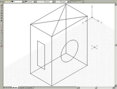
Fig Tsk 8.
Without exiting the model, save it the way you would usually save a 2D drawing. If you wish to leave AutoCAD at this point, exit in the usual way. On your return, call up the model as you would for a 2D drawing.
Please feel welcome to make use of the free resources at the side and bottom of these webpages. Many of them contain very useful 3D CAD material.


For a negligible fee (about the cost of a large cola drink) the full course AND CERTIFICATE can be printed in one go. The small sums it raises cover our costs for running the site. Click here for details.